MMIQ-0520LS
Low LO Drive Passive GaAs MMIC IQ Mixer
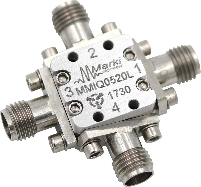
MMIQ-0520L is a low LO drive, passive GaAs MMIC IQ mixer that operates down to an unrivaled +3 dBm LO drive level. This is an ultra-broadband mixer spanning 5 to 20GHz on the RF and LO ports with an IF from DC to 6 GHz. Up to 40 dB of image rejection is available due to the excellent phase and amplitude balance of its on-chip LO quadrature hybrid. Both wire bondable die and connectorized modules are available.
Technical Resources
 Datasheet
 Application Notes
 Part Number Decoder
Product Status: Released
 Tools
Tools White Papers
 Materials Compliance
 Product Search Tool
 Related Products
 Contact
Us
Contact
Us