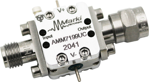
<style type="text/css"> .wpb_animate_when_almost_visible { opacity: 1; }</style>

The electrical specifications apply at TA=+25°C in a 50Ω system.

Min and Max limits apply only to our connectorized units and are guaranteed at TA=+25°C.  Die are 100% DC tested and RF tested on a per lot basis

Parameter

Test Conditions

Frequency

Min

Typical

Units

Saturated Output Power[1]

3V/-0.5V bias

11 GHz – 15 GHz


+19

dBm

15 GHz – 30 GHz

+17

+21

30 GHz – 38 GHz


+17

Small Signal Gain

3V/-0.5V bias

11 GHz – 15 GHz


20

dB

15 GHz – 30 GHz

17

20.5

30 GHz – 38 GHz


15.5

Input Return Loss

3V/-0.5V Bias

11 GHz – 38 GHz


18

Output Return Loss

11 GHz – 38 GHz


12

Reverse Isolation

11 GHz – 38 GHz


53

Noise Figure

3V/-0.5V bias

11 GHz – 38 GHz


5.8

Bias Requirements[2]

3V/-0.4V

-


230

mA

3V/-0.5V

-

180

3V/-0.6V

-

130

Input IP3 (IIP3)

3V/-0.5V,

-20 dBm Input Power

11 GHz – 38 GHz


12

dBm

Output IP3 (OIP3)

11 GHz – 38 GHz


31

Output P1dB

3V/-0.5V bias

11 GHz – 38 GHz


18

Input Power for Saturation

3V/-0.5V bias

11 GHz – 38 GHz


+6

dBm


[1] Saturated Output Power specification defined using the AMM-7199UC P5dB compression curve shown in section 3.7.

[2] Bias conditions tested with no RF input power. Bias conditions presented as Vd/Vg.

Download our 3D models here.
AMM-7199 Amplifier Package Diagram
The AMM-7199 is a general-purpose broadband MMIC driver amplifier that provides +21 dBm output power suitable for driving a Marki H or L diode mixer at 11-38 GHz and S diode mixer from 15-32 GHz. The amplifier also has excellent return losses and gain flatness. The small die size allows it to be used in a variety of applications, and has built in DC-blocking capacitors on the input and output.

ModelPackageOrder
AMM-7199CHChip (CH)Buy Now
AMM-7199UCConnectorized (UC)Buy Now


Did you know we offer high-performance Adapters, Attenuators, DC Blocks, and Power Limiters?

START TYPING AND PRESS ENTER TO SEARCH FOR MARKI PRODUCTS.