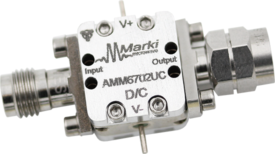
<style type="text/css"> .wpb_animate_when_almost_visible { opacity: 1; }</style>

AMM-6702CH and AMM-6702UC Electrical Specifications

The electrical specifications apply at TA=+25°C in a 50Ω system. Min and Max limits apply only to our connectorized units and are guaranteed at TA=+25°C.

Parameter

Test Conditions

Frequency

Min

Typical

Units

Saturated Output Power

3.0V/-0.5V Bias

21 GHz – 55 GHz


+19

dBm

3.5V/-0.5V Bias

21 GHz – 25 GHz


+20

25 GHz – 48 GHz

+17

+21

48 GHz – 55 GHz


+17

4.0V/-0.5V Bias

21 GHz – 55 GHz


+20

Small Signal Gain

3.0V/-0.5V Bias

21 GHz – 55 GHz


24

dB

3.5V/-0.5V Bias

21 GHz – 25 GHz


25

25 GHz – 48 GHz

20

24

48 GHz – 55 GHz


22

4.0V/-0.5V Bias

21 GHz – 55 GHz


23

Input Return Loss

3.5V/-0.5V bias, ‑25 dBm Input Power

21 GHz – 55 GHz


8

Output Return Loss


9

Noise Figure


6.5

Reverse Isolation


45

Bias Requirements[1]

3.5V/-0.6V


130

mA

3.5V/-0.5V


180

3.5V/-0.4V


230

Input IP3 (IIP3)

3.5V/-0.5V bias, -25 dBm Input Power

21 GHz – 55 GHz


+3

dBm

Output IP3 (OIP3)


+27

P1dB

3.5V/-0.5V bias


+14.8

Input Power for Saturation

3.5V/-0.5V bias


+3

AMM-6702UC5 Electrical Specifications

The electrical specifications apply at TA=+25°C in a 50Ω system. Min and Max limits apply only to our connectorized units and are guaranteed at TA=+25°C.

Parameter

Test Conditions

Frequency

Min

Typical

Units

Saturated Output Power

+5V bias, +5 dBm Input Power

21 GHz – 25 GHz


+20

dBm

25 GHz – 48 GHz

+17

+21

48 GHz – 55 GHz


+17

Small Signal Gain

+5V bias, -25 dBm Input Power

21 GHz – 25 GHz


25

dB

25 GHz – 48 GHz

20

24

48 GHz – 55 GHz


22

Input Return Loss

+5V bias, -25 dBm Input Power

21 GHz – 55 GHz


8

Output Return Loss


9

Noise Figure


6.5

Reverse Isolation


45

Bias Requirements[2]

+5V


230

mA

Input IP3 (IIP3)

5V bias, -25 dBm Input Power

21 GHz – 55 GHz


+3

dBm

Output IP3 (OIP3)


+27

P1dB

+5V Bias


+14.8

Input Power for Saturation


+3


[1] Bias conditions tested with no RF input power.  See section 3.6 for DC current vs. RF power

[2] Bias conditions tested with no RF input power.  See section 3.6 for DC current vs. RF power

Download our 3D models here.
AMM-6702 Amplifier Package Diagram
The AMM-6702 is a broadband MMIC LO buffer amplifier that efficiently provides high gain and output power over a 21-55 GHz frequency band.  It is designed to provide a strong, flat output power response when driven with an input power at 0 dBm.  It has built-in DC blocking capacitors on the input and output.

ModelPackageOrder
AMM-6702CHChip (CH)Buy Now
AMM-6702UCConnectorized (UC)Buy Now
AMM-6702UC5Connectorized (UC5)Buy Now


Did you know we offer high-performance Adapters, Attenuators, DC Blocks, and Power Limiters?

START TYPING AND PRESS ENTER TO SEARCH FOR MARKI PRODUCTS.